FAQ
General:
- Can the 3DM-GQ7 operate globally?
- Is the 3DM-GQ7 IP rated?
- Should I use Serial or USB?
- Do settings get erased from the 3DM-GQ7 if I unplug it?
- How do I upgrade firmware?
GNSS:
- Can I use a different GNSS antenna than the default U-Blox antenna?
- Does the 3DM-GQ7 have anti-spoofing or anti-jamming capability?
- How do I measure the antenna offsets?
- What are the mounting requirements for using Dual-Antenna heading?
- How do I improve dual antenna heading performance?
RTK:
- Is the 3DM-GQ7's RTK solution guaranteed?
- Is the SensorCloud RTK corrections stream guaranteed?
- Do I need to use the 3DM-RTK and SensorCloudRTK to receive RTK corrections?
Navigation Filter:
- Why is the filter stuck in Vertical Gyro Mode?
- How do I improve Navigation Filter performance?
- How do I know when I can trust the Navigation Filter solution?
- How do I interpret the Filter Status (0x82,0x10) message?
- Can the 3DM-GQ7 navigate during a GPS outage?
External Measurements:
- What type of odometer is required to provide a GPIO odometry input to the Navigation Filter?
- Can I input LIDAR or Radar measurements into the Navigation Filter?
- I don’t have wheeled odometry but I have and want to provide a speed measurement to the 3DM-GQ7. Is this possible?
Data:
Support
Software:
- Does Microstrain by HBKhave data visualization tools?
- Does Microstrain by HBK have ROS drivers?
- Does Microstrain by HBK have PX4 drivers?
- Does Microstrain by HBK have ArduPilot drivers?
Miscellaneous:
General
Can the 3DM-GQ7 operate Globally?
- Yes, the 3DM-GQ7 is not ITAR controlled.
- We have support for GPS/QZSS, GLONASS, and Galileo. BeiDou support is scheduled for a future release.
- If using RTK, SensorCloudRTK has coverage in many locations around the world. Check the Coverage Map for more info.
Should I use Serial or USB?
- Serial provides low, predictable data latency, but is bandwidth limited at lower baudrates, such as 115200.
- USB provides better bandwidth but the operating system is in charge of pulling data from the device, potentially causing delays in packet delivery.
- This delay can be mitigated by using the hardware PPS signal to time synchronize multiple devices and/or the GPS timestamp, available for all device data streams, for time synchronization.
- Many OEM customers elect to use USB + PPS to stream data from the Navigation Filter at speeds greater than 250Hz (up to 1kHz).
- See Communications Bandwidth Management for more info.
Is the 3DM-GQ7 IP rated?
- No, it has a ruggedized, dust resistant enclosure.
- An IP67 or IP68 version is under consideration for the future. Please contact sales if you require one of these options.
Do settings get erased from the 3DM-GQ7 if I unplug it?
- It depends. The 3DM-GQ7 will use the existing "startup settings” stored in the device unless the settings are saved prior to power down. To save the settings, do one of the following:
- In SensorConnect, click “Save as Startup Settings” in the “Save/Load” tile.
- In SensorConnect, click the checkbox “Save as Startup Settings” in the “Streaming” tile.
- In ROS, set the "save_settings" param to true and successfully launch the node
- In MSCL, use the node.saveSettingsAsStartup() function.
- Use the Device Settings (0x0C,0x30) command with the SAVE function selector.
- In SensorConnect, you can also export a .json settings file to your local computer that will save your full device configuration, which can be loaded again in the future.
How do I upgrade firmware?
-
Please see the Firmware Upgrades page for methods and instructions on upgrading device firmware.
GNSS
Can I use a different GNSS antenna than the default U-Blox antenna?
- Performance of the 3DM-GQ7is only guaranteed with the U-Blox ANN-MB.
- Dual-Antenna and/or RTK functionality require dual band antennas as noted on the Antenna(s) page. The 3DM-GQ7requires both the L1 and L2 GNSS bands to use either of these features.
- GNSS Frequency bands supported by the 3DM-GQ7: L1C/A, L2C, L1OF, L2OF, E1B/C, E5b, B1I, B2I
- A 3rd party antenna must be powered and require the same or less power from the 3DM-GQ7 as listed under the Electrical Characteristics section of the Electrical specifications page and repeated below, or have external power supplied to meet the specification:
- 3V, 100mA
- If you wish to use an antenna that requires more power, the following Bill of Materials provides a list of required parts with example antennas.
- If using an antenna that terminates in an SMA connector, it is recommended to use double-shielded adapter cables for EMI mitigation. Our test team has found these cables to be satisfactory.
NOTE: ensure gender compatibility of connectors when purchasing.
We have tested and recommend the following antennas for use with the 3DM-GQ7:
-
-
The following Bill of Materials provides a list of required parts with these antennas.
-
Does the 3DM-GQ7 have anti-spoofing or anti-jamming capability?
-
As of firmware version 1.1.02, the 3DM-GQ7 has spoofing and jamming detection/monitoring indicating the level of measured RF interference. If a 3DM-GQ7 has an earlier version of firmware, its must be upgraded to employ this feature. This may be accomplished through SensorConnect's Firmware Upgrade tile for Windows, or the Command Line Firmware Upgrade tool for Linux (coming soon).
-
This feature does not provide active anti-spoofing or anti-jamming. The device reports one of four possible states of jamming and/or spoofing (Unknown, None, Partial, Significant) for each RF band.
-
The navigation filter does not reject GNSS measurements based on this information, but does use other signal quality metrics to screen signals prior to using them.
-
The user can monitor the status of this information in the RF Error Detection Field messages for each receiver: RF Error Detection (0x91,0x14), and RF Error Detection (0x92,0x14) .
-
Spoofing Detection: the 3DM-GQ7 will monitor suspicious changes in the GNSS signal that indicate external manipulation. Spoofing detection will only be successful when initialized with an unaltered GNSS lock. If the GNSS signal is spoofed, the RF Error Detection field will provide notification that the GNSS signal is no longer genuine. The algorithm used relies on availability of signals from multiple GNSS constellations.
-
Jamming Detection: can be used as an indicator for continuous wave (narrow-band) or broadband jammers/interference. If jamming is indicated, the user should act in a manner that is appropriate for their application. Note: jamming may be reported if the user’s system is generating enough EMI to trigger the indication. In this instance, it is recommended the user take actions to reduce this EMI.
How do I measure the antenna offsets?
- Please review the How to Measure Antenna Offsets section of the Antenna(s) page.
What are the mounting requirements for using Dual-Antenna heading?
- Review the Antenna(s) page.
- Proper antenna mounting and lever arm measurement are critical to maximizing heading performance. The baseline, or the horizontal distance in between the antennas, dictate the maximum accuracy of the solution. The antenna baseline length is limited to:
- Min: 0.25m
- Max: 5.0m
- Typical is 1 - 2m
- If using dual antenna or RTK, each antenna lever arm offset should be accurate to within 5cm.
Figure: Antenna Baseline vs Maximum Accuracy
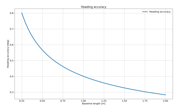
Heading accuracy as a function of baseline length under ideal conditions
How do I improve dual antenna heading performance?
- Improve precision of antenna installation:
- Review the Antenna(s) page for best practices and helpful tips and follow steps 1-3 of Antenna Mounting Considerations.
TIP: The simplest method for testing is to colinearly mount the 3DM-GQ7 and GNSS antennas on the same piece of material ex: car roof, piece of rigid wood with ground planes, piece of flat rigid metal.
- Increase antenna baseline (up to 5 meters, 1-2 meters typical.)
- Ensure both antennas have a clear view of the sky.
- Minimize any sources of multipath, including multipath coming from the vehicle itself. Mounting the antennas above all other objects on the vehicle is the preferred way to minimize interference.
- Minimize EMI exposure for both the antennas and their cabling.
RTK
Is the 3DM-GQ7's RTK solution guaranteed?
- For a valid RTK fix, both a consistent RTCM corrections stream and a clear sky view is required. If the correction stream is interrupted or the device moves through a challenging GNSS environment, the RTK fix could be interrupted.
Is the SensorCloud RTK corrections stream guaranteed?
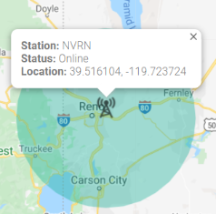
- We simplify the network and interface process to provide you an all-in-one navigation solution. This solution includes our 3DM-GQ7, 3DM-RTK and SensorCloudRTK service. We work with RTK and cellular providers to deliver the SensorCloudRTK service. As we do not own those provider’s networks we cannot control their operational behavior. SensorCloudRTK Coverage Map provides a real-time database showing base stations' ID, location, operational status and range as shown in Figure: SensorCloudRTK Example Base Station Info
Figure: SensorCloudRTK Example Base Station Info
Do I need to use the 3DM-RTK and SensorCloudRTK to receive RTK corrections?
- No, we have outlined several ways for the 3DM-GQ7 to receive RTK corrections in the "4 Ways to RTK" app note and many more have been added since.
- For ROS users, head to the ROS NTRIP client node, compatible with our ROS1 and ROS2 drivers.
Navigation Filter
Why is the filter stuck in Vertical Gyro Mode?
- The filter is likely stuck in Vertical Gyro Mode because it does not have sufficient initial conditions. See Filter States for more info on Vertical Gyro Mode.
- In Vertical Gyro Mode, the Navigation Filter is only reporting valid gyro stabilized pitch, roll, and the change in heading relative to the initial orientation. To transition to Full Navigation mode, the Navigation Filter requires the initial conditions for all states shown in the table below. These can be provided to the Navigation Filter through the Initialization Configuration (0x0D,0x52) command. The time to transition from power on to Full Navigation mode under ideal conditions is typically less than
| Filter Mode | Filter State Value | Initial Conditions Required | Available Outputs |
|---|---|---|---|
| Initialization | 1 | None | None |
| Vertical Gyro | 2 | Roll, Pitch (from IMU) | Roll, pitch, relative heading |
| AHRS | 3 | Absolute heading | Roll, pitch, absolute heading |
| Full Navigation | 4 | Absolute heading, initial position, initial velocity | Roll, pitch, absolute heading, position, velocity |
- Ensure 3DM-GQ7 is configured correctly - see Filter Aiding Measurements and Filter Initialization.
- If the 3DM-GQ7 hasn't converged in
How do I improve Navigation Filter performance?
The time to transition to the Full Navigation filter mode is less than
- Ensure that your firmware is updated to the latest version.
- Ensure antennas are correctly installed, and if using dual antenna, that their offsets are not accidentally swapped (a common problem).
- Ensure the proper Filter Aiding Measurements are enabled.
-
How do I know when I can trust the Navigation Filter solution?
It is highly recommended to read the Navigation Filter section of the manual. You will need to configure the device to stream the data fields that contain the status information required for your application. Upon receipt of the status fields, you will need to set thresholds for the data based on your application's requirements, for example:
- The Status (0x82,0x10) message provides two important pieces of information for the user: the current Filter State (AKA mode) and Status Flags that provide real-time warnings about the filter's condition and its estimates.
- The Status (0x82,0x10) message will report values of 4, 1, 1, when the Navigation Filter is in normal operation. These numbers correspond to Full Navigation Filter State, Default Dynamics Mode, and Converged filter Status Flags.
- See "Interpreting the Status data channel" below for more info.
- Filter Position Uncertainty Messages
- The user must decide what position uncertainty values are required for their application. Typical 1σ values are:
- Single point: 1.25-2.5m
- RTK-Float: 0.1- 0.8m
- RTK-Fixed: 0.01 - 0.06m (error model assumes maximum base station baseline of 50 km)
- Position uncertainty is available in different frames in the following messages:
- The user must decide what position uncertainty values are required for their application. Typical 1σ values are:
- GNSS Position Aiding Status (0x82,0x43)
- Check for desired GNSS position aiding measurements:
- If RTK Float is required, check for differential corrections (bit 1 is set)
- If RTK Integer Fix is required, check for integer fix (bit 2 is set)
- If a specific constellation and frequency are required, for example Galileo E1 , check the corresponding bit, ex GAL_E1 (bit 8 is set)
- Check for desired GNSS position aiding measurements:
- Euler Angles Uncertainty (0x82,0x0A)
- Set application specific Yaw (heading) uncertainty threshold
- Verify uncertainty is below threshold
- Dual Antenna Status (0x82,0x49)
- Verify fix type is FIX_DA_FIXED = 2
- Verify heading uncertainty is below required threshold
- Verify all desired Status Flags are valid before trusting the heading estimate.
How do I interpret the Status (0x82,0x10) message?
The data fields reported by the Status (0x82,0x10) message are the Filter State, Dynamics Mode, and Status Flags. The Status Flags is a bitfield that must be properly interpreted:
- SensorConnect's Status QuickView performs the conversion for the user into easy to understand text.
- The ROS drivers RQT Status QuickView GUI performs the conversion for the user into easy to understand text.
- If converting manually, a simple online decimal to binary converter or calculator application in "programmer mode" will work.
- For embedded applications, a simple bitshift calculation is required.
- We recommend the user checks for the Filter state = 0x04 and Status flags = 0x01 or 0x02 (i.e. no warnings are raised and the filter condition is either stable or converging) at minimum to verify satisfactory filter performance.
Ex: What does 4, 1, 1025 mean from Status (0x82,0x10)?
- One can use any decimal to binary converter, we see the 0th and 10th bit have values of 1.
- The 0th and 1st bits correspond to the Filter Condition,as described on the Filter Status Flags page. The 0th bit indicates a Filter condition of Stable. This is desired so is not the cause of concern.
- The 10th Status Flag bit corresponds to a time sync warning as seen in the table below with the 10th bit's row highlighted in yellow. This means no PPS source is detected and the recommended action is to check the PPS source is set correctly i.e. ensure an antenna is connected for the PPS source selected.
| Bit # | Bit Value | Description | Potential Cause | Recommended Action |
|---|---|---|---|---|
| 0-1 | 1 | Filter condition (Stable/Converging/Unstable) | Insufficient initial conditions supplied. | Verify required conditions are properly enabled. Review Filter States. |
| 2 | 0 | Roll/Pitch Warning | Sensor is not aligned with vehicle frame. | Review Vehicle Frame page. |
| 3 | 0 | Heading Warning | Heading source is not valid. For Dual Antenna: Multipath, EMI, incorrect antenna offsets. For Magnetometer:time varying magnetic interference. |
|
| 4 | 0 | Position Warning | Multipath, EMI, incorrect antenna offsets, antennas obstructed, antenna cable shorted. Review How to improve filter performance above. | Review: Antenna offsets, FAQ: Antenna sections, FAQ:How to improve filter performance. |
| 5 | 0 | Velocity Warning | ||
| 6 | 0 | IMU Bias Warning | Gyro bias is high. | Perform Capture Gyro Bias (0x0C,0x39) |
| 7 | 0 | GNSS Clock Warning | Multipath, excessive vibration. | Not critical concern - continue navigation. |
| 8 | 0 | Antenna Lever Arm Warning | Antenna Lever Arm offsets are likely incorrect. |
|
| 9 | 0 | Mounting Transform Warning | Transform is likely incorrect. | Review Vehicle Frame page. |
| 10 | 1 | Time Sync Warning | No PPS source detected. | Check PPS source is set correctly i.e. GNSS receiver 1 = PPS 1 |
| 12-15 | 0 | Solution Error | Filter computation warning flags. If any bits 12-15 are set, all filter outputs will be invalid. | Reset Navigation Filter (0x0D,0x01) |
- Note: the filter condition occupies 2 bits (bits 0 and 1) and can be interpreted as shown below (see Filter Status Flags page for more info).
| Filter Condition Values | Description |
|---|---|
| 1 | Stable |
| 2 | Converging |
| 3 | Unstable/Recovering |
Can the 3DM-GQ7 navigate during a GNSS outage?
-
- In cases where outages longer than 60 seconds are expected, and depending on the position accuracy requirements of the application, we typically recommend using additional
- For UAS and USV higher uncertainties may be allowable in which case the user may continue to navigate without these aiding measurements, while monitoring the navigation solution as described above. The 3DM-GQ7 can continue to navigate but its position error will increase exponentially, as is the case on the majority of INS systems.
- We have multiple test reports that show the 3DM-GQ7’s performance during, and recovery from GNSS outages:
- GNSS Outage Test Report:
- 60s GNSS outage in a wheeled-vehicle with the following configurations: no constraints; with Wheeled Vehicle Constraint (WVC); with WVC and Wheeled Odometry
- GQ7 vs GX5 Product Comparison Test Report:
- 60s GNSS outage in a wheeled-vehicle using RTK + Wheel Odometry
- Benefits of a Tactical IMU in a GNSS/INS:
- 30s GNSS outage while driving in a wheeled-vehicle, specifically comparing the impact of IMU quality on the solution
- GNSS Outage Test Report:
External Measurements
What type of hardware odometer can I use for the odometry input?
- The 3DM-GQ7 currently supports quadrature (dual channel) encoders. Single ended encoder support may be added depending on demand.
- The 3DM-GQ7 has been tested with the following odometer: Michigan Scientific High Resolution Wheel Pulse Transducer E512
Can I input LiDAR, Radar, or Pitot data into the Navigation Filter?
While the 3DM-GQ7 does technically have the commands to accept these external aiding measurements as general inputs, it is not recommended as the 3DM-GQ7's interface and EKF is not well equipped to accept them. These shortcomings have been addressed in the 3DM-GV7-INS, and 3DM-CV7-INS through their flexible external aiding measurement interface.
I don’t have a wheel odometry hardware encoder but I have and want to provide a speed measurement to the 3DM-GQ7. Is this possible?
- No, unfortunately this is not supported on the 3DM-GQ7 but is supported on the 3DM-CV7-INS and 3DM-GV7-INS.
Data
Is the bias removed from Compensated Angular Rate (0x82,0x0E) and Compensated Acceleration (0x82,0x1C) data channels?
Yes, but the Compensated Angular Rate or Compensated Acceleration messages are not anti-aliased at this time. This means, if you choose a sample rate lower than 500 Hz, aliasing can occur, which looks like noise but is actually due to down-sampling. This shortcoming is being addressed in the next firmware release.
Support
How do I obtain Engineering Support for my device ?
MicroStrain Support Engineers can be contacted through many methods. Please review the Support page for more information.
Software
Do you have data visualization tools?
Does Microstrain by HBK have ROS drivers?
Yes, and we have examples, and a dedicated ROS Engineer to support them and support you! See the Software page for more information.
Does Microstrain by HBKhave PX4 drivers?
Yes! Please see the Software page for more information.
Does Microstrain by HBKhave ArduPilot drivers?
Yes! Please see the Software page for more information.
Miscellaneous
Does the 3DM-GQ7 publish a GPGGA NMEA string?
-
3DM-GQ7s with firmware versions equal to or greater than 1.1.02 support selected NMEA-0183 sentences over the Main port. See NMEA Output for details.
-
For firmware versions less than 1.1.02, the 3DM-GQ7 does publish the GPGGA NMEA string from the AUX Port under the following conditions:
-
The GNSS RTK dongle configuration is enabled via the MIP GNSS RTK Dongle Configuration (0x0E,0x10) command.
-
The device has at least one GNSS Antenna connected with a fix.
NOTE: By enabling the dongle as above, an additional MIP message is generated by the GQ7 at 1 Hz that is sent with the GPGGA NMEA string. It is assumed that the receiving device/service is able to ignore this binary data.
-