Electrical
Pin Definitions
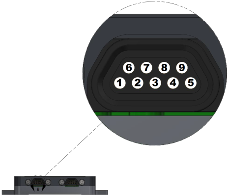
All pins referred to in the tables below can be found on the MAIN and AUX connectors.
|
|
See User GPIO for details on how to use the GPIO pins and supported features.
Absolute Maximum Ratings
Exposure to stresses beyond those listed under Absolute Maximum Ratings may cause permanent damage to the device. Exposure to the Absolute Maximum Ratings for extended periods may affect device reliability and lifetime. Absolute Maximum Ratings are stress ratings only and do not imply functional operation of the device under any conditions beyond those listed in Recommended Operating Conditions.
| Pin | Specification(1) | Notes | Min | Max | Units |
|---|---|---|---|---|---|
| Vpri | Input Voltage | Also protected against ESD and other high-voltage / low-energy transients. | -0.3 | 24 | V |
| Vaux | -0.3 | 24 | V | ||
| RS-232 Tx | Input Voltage | -15 | 15 | V | |
| RS-232 Rx | -25 | 25 | V | ||
| USB D- | Input Voltage | -0.3 | 7 | V | |
| USB D+ | -0.3 | 7 | V | ||
| GPIOs | Input Voltage Range | Device powered off or internal pullup enabled | -0.3 | 3 | V |
| Device powered on and internal pullup disabled | -0.3 | 6.0 | V | ||
| Input Injection Current | GPIO not set to output | -5 | 5 | mA | |
| Output Current | GPIO set to output | -25 | 25 | mA | |
| GNSS Antenna Ports | DC Load Current | 0 | 100 | mA |
Notes:
- All voltages referenced to ground.
Recommended Operating Conditions
Stresses beyond the limits in Recommended Operating Conditions will likely result in the improper functioning of the device. The voltages in Recommended Operating Conditions represent voltages as measured at the pins; they do not account for voltage drops in the cable.
| Pin | Specification(1) | Notes | Min | Typ | Max | Units |
|---|---|---|---|---|---|---|
| Vpri | Input Voltage Range | 4.2 | 16 | V | ||
| Vaux | Input Voltage Range | 4.2 | 16 | V | ||
| USB D- | Input Voltage | Connect to USB host only, or leave disconnected | 0 | 5.5 | V | |
| USB D+ | 0 | 5.5 | V | |||
| GPIOs | Input Voltage Range | Device ON, pullup disabled | 0 | 5 | V | |
| Load Capacitance | Any output mode | 5 | pF | |||
| Output Current | -8 | 8 | mA | |||
| Antenna ports | DC Load Current | 50 | mA |
- All voltages referenced to ground.
Power Requirements
The 3DM-GQ7 can be powered through either the Vpri or Vaux pin. See Powering for details.
| Specification | Notes | Min | Typ | Max | Units |
|---|---|---|---|---|---|
| Operating Voltage | As measured at Vpri or Vaux pin. Does not account for voltage drops in the cable. | 4.2 | 16 | V | |
| Power Consumption | 2.0 | 2.5 | W |
Electrical Characteristics
| Pin | Specification(1) | Notes | Min | Typ | Max | Units |
|---|---|---|---|---|---|---|
| RS-232 Tx | Output High | 5 | 6.2 | V | ||
| Output Low | -5.7 | -5 | V | |||
| RS-232 Rx | Input High Threshold | 1.7 | 2.5 | V | ||
| Input Low Threshold | 0.8 | 1.3 | V | |||
| GPIOs | Output Low Voltage | Any output mode | 0.0 | 0.0 | 0.36 | V |
| Output High Voltage | 1.4 | 3.0 | 3.0 | V | ||
| Non-PPS input low threshold | 1.12 | V | ||||
| Non-PPS input high threshold | 0.785 | V | ||||
| PPS input low threshold | 0.8 | V | ||||
| PPS input high threshold | 2 | V | ||||
| PPS output rise time | 15 | nS | ||||
| PPS output fall time | 15 | nS | ||||
| PPS accuracy | 1 sigma = 30, 3 sigma = 60 | nS | ||||
| Antenna Ports | DC Output Voltage | 2.9 | V | |||
- All voltages referenced to ground.