Antenna(s)
Antenna Type
Both single frequency (L1) and multi-frequency (L1/L2) GNSS antennas can be used with the 3DM-GQ7. However, a GNSS antenna with multi-frequency capability is required for RTK and/or dual antenna functionality.
Antenna Mounting Considerations
Proper installation of GNSS antennas is critical to GNSS/INS performance. To get the best GNSS performance possible, there are many RF considerations that must be taken into account. The following methods can be used to optimize performance:
1. Mitigate Multipath:
- Ensure the GNSS antennas have an unobstructed sky view. Even materials like plastic and glass can attenuate the GNSS signal and should not be placed between the antenna and the sky unless it is known they will not interfere with GNSS signal reception.
- Ensure the sky view from the GNSS antennas is not obstructed by trees or buildings. A “good” sky view is >45° in all directions from the vertical.
- Ensure the sensitive axis of the antenna is facing vertical towards the sky (z-axis aligned with vertical.)
![]()
- Install ground planes under each antenna: a ~10x10cm metallic ground plane under each antenna to reject multipath is recommended. This simple groundplane can be purchased from Sparkfun. (For more information on OEM ground plane design, see pg. 17 in u-blox GNSS Antennas App Note and pg. 7 of u-blox ANN-MB Datasheet)
- Ensure that there is a minimum of 3 centimeters of clearance around the circumference of the antenna.
2. Check antenna offsets:
- Ensure antenna offsets are correctly entered and are not swapped (a common problem.) See How to Measure Antenna Offsets section below.
3. Mitigate EMI:
 WARNING: Even low levels of EMI can significantly degrade GNSS performance and must be considered when choosing an antenna mounting location.
- Common EMI sources are Electric motors, computers, modems, power supplies, unshielded data lines, cameras, LIDAR, compute boxes, relays.
- Mount the antennas as far away as possible from EMI Sources.
- Route cables as far away as possible from EMI Sources.
- Minimize cable length, ensuring to maintain cable integrity with strong solder joints and verify antenna cable is not shorted. For OEM applications, contact sales for custom cable lengths.
- Store any excess coiled GNSS cable away from EMI sources as coiled cable can act as an antenna and introduce significant EMI.
- For OEM designs, ensure antennas are mounted following manufacturers specification. If using the default U-Blox antennas, consult sections 5 and 6 of the antenna design guide.
- If none of the above fixes the performance issues, contact Microstrain by HBK customer support for a more detailed analysis of the application.
TIP: GNSS quality metrics such as position uncertainty can be used to identify EMI. Toggle power to the system suspected of generating EMI and monitor the effects on the position uncertainty. If the uncertainty increases when the system powers on, it could be impacting GNSS performance.
PPS Source
If using a single antenna, it is recommended to connect the primary antenna to antenna port 1 on the 3DM-GQ7, because the PPS source selector (PPS Source (0x0C,0x28))defaults to GNSS 1.
Secondary GNSS Antenna Mounting
A second GNSS antenna is only required if using GNSS dual antenna aiding (see
Figure: Dual - Antenna Baseline vs Accuracy
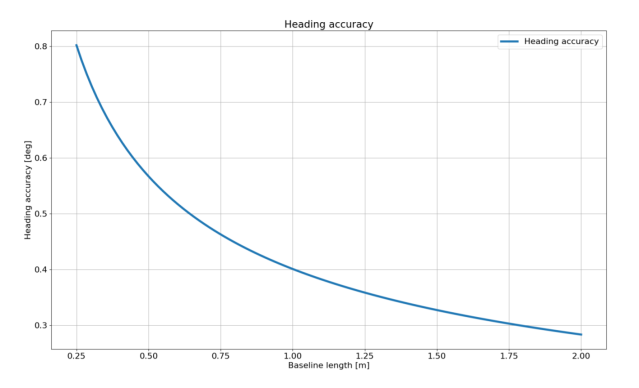
Heading accuracy as a function of baseline length under ideal conditions
How to Measure GNSS Antenna Offsets
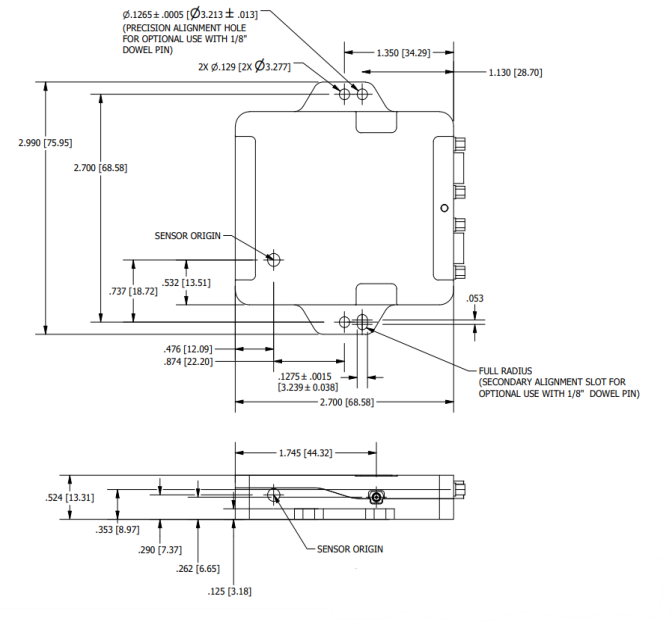
The GNSS antenna offsets must be measured and provided to the 3DM-GQ7 through the . The antenna offsets are measured with respect to the Vehicle Frame from the SENSOR ORIGIN of the 3DM-GQ7 to the antenna phase center of the
GQ7 Mechanical Drawing: SENSOR ORIGIN
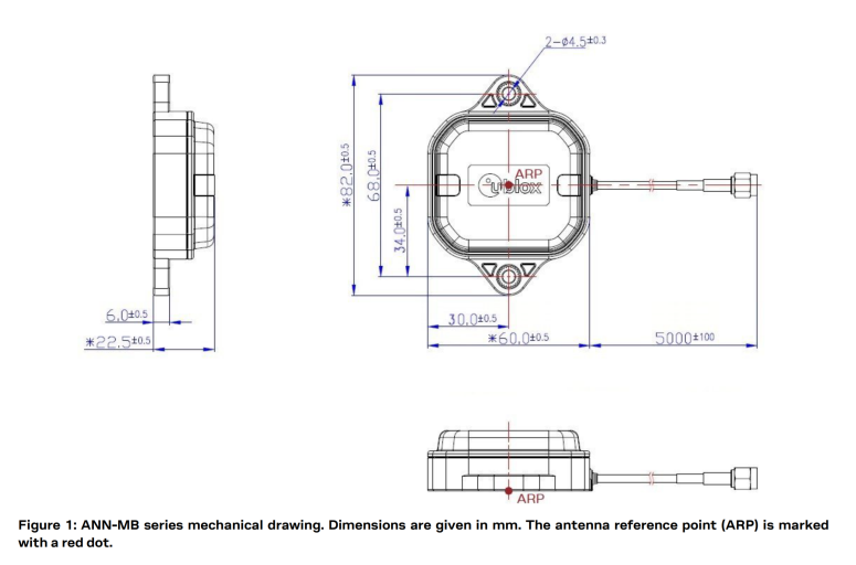
u-blox ANN-MB Mechanical Drawing: Antenna Reference Point
Example: Measuring the GNSS Antenna Offsets in the Vehicle Frame
The following example illustrates how to measure the antenna offsets and use the
Vehicle Frame Axes:
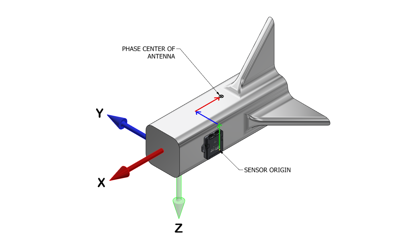
In this example, the green arrow shows the offset along the z-axis of the vehicle frame. It starts at the SENSOR ORIGIN and points in the negative z direction. The blue arrow represents the offset along the y-axis the vehicle frame. It is in the positive y direction. The red arrow represents the offset along the x-axis of the vehicle frame. It is in the negative x direction.
The table below uses some fictional magnitudes to detail the parameters that would be entered into the GNSS Multi Antenna Offset Control (0x0D,0x54) command. The signs are correct for the above example.
NOTE:When using this command, a user must specify which antenna (1 or 2) these offsets are being applied to.
| GNSS Multi Antenna Offset Control (0x0D,0x54) Command Parameters | Values | Units |
|---|---|---|
| X offset | -0.32 | meters |
| Y offset | 0.11 | |
| Z offset | -0.64 |
Antenna Lever Arm Calibration
Antenna offset error can be introduced by inexact offset measurements and by the fact that the phase center of an antenna does not always correspond to its physical center. These errors can, in turn, produce positioning and heading errors. The GNSS Antenna Cal Control (0x0D,0x64) command can be used to enable active tracking of these errors in the Navigation Filter. For the 3DM-GQ7, the maximum offset error defaults to 0.1 meters. The maximum offset that can be entered is 0.5 meters.
| GNSS Antenna Cal Control (0x0D, 0x64) | |
|---|---|
| Maximum Offset | 0.5 meters |
| Default Offset | 0.1 meters |