Gated Data Streaming using a GPIO
In this example, we’ll show how to configure the 3DM-CV7 to stream scaled accelerometer, scaled gyro, and filtered Euler angles at 100 Hz only when a GPIO pin is pulled low. The data stream will stop when the GPIO is pulled high.
NOTE: This example can be easily adapted to the 3DM-CV7 by substituting GPIO 1 or GPIO 2 for GPIO 3.
Hardware Setup
For this example, we’ll assume there is a function generator connected to GPIO 3. The generator should be set for a square wave with the high voltage at 3 volts and the low voltage at 0. The frequency should be less than 2 Hz for easy observation. Leave the output disabled for now.
With slight modification, a jumper wire or push button can be used instead. Leave the wire floating on GPIO 3, or connect the button between GPIO 3 and ground.
To accommodate either situation, we’ll set it up to enable streaming when the pin reads low.
GPIO Trigger Configuration
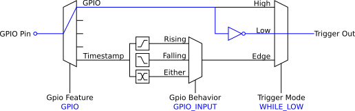
In this example, we’ll use a Trigger: GPIO in “state” mode on GPIO 3 set to activate while the pin is in the low state.
Configure the trigger
Use the Event Trigger Configuration (0x0C,0x2E) command to configure trigger 1 for GPIO.
- Function: WRITE (0x01)
- Instance: 1
- Type: GPIO (0x01)
- Parameters:
- Pin: 3
- Mode: WHILE_LOW (0x02)
Command bytes: 0101010302
MIP Packet: 75650c07 072e0101010302 2af6
GPIO Setup
Since we’ll be using a GPIO pin in this example, it needs to be configured with the GPIO Configuration (0x0C,0x41) command for GPIO Input mode. We’ll enable the built-in pull-up resistor to ensure the pin floats high when disconnected. This helps avoid unintentional triggers when using a push button or jumper wire, or any time the pin can only be pulled low by the connected system.
- Function: WRITE (0x01)
- Pin: 3
- Feature: GPIO (0x01)
- Behavior: GPIO_INPUT (0x01)
- Pin Mode: Pullup (0x04)
Command bytes: 0103010104
MIP Packet: 75650c07 07410103010104 3f6e
Check the trigger is working
Enable the trigger
Since triggers are disabled by default, it must be enabled. Use the 3DM Event Control (0x0C,0x02B) command to enable it.
- Function: WRITE (0x01)
- Instance: 1 (this is the trigger ID used previously)
- Mode: ENABLED (0x01)
Command bytes: 010101
MIP Packet: 75650c05 052b010101 1e82
Check the status
The Get Trigger Status (0x0C,0x2C) command can report the status of the newly-configured and enabled trigger.
Command:
- Requested Count: 1
- Requested Instances: [1] (this is the trigger ID used previously)
Command Bytes: 0101
MIP Packet: 75650c04 042c0101 1c5e
Reply Packet: 75650c09 04f12c00 05b6010102 cf63
Response data: 010102
- Count: 1
- Type: 0x01 (GPIO)
- Status: 1 (enabled)
Turn on the function generator and issue the command a few more times until you see status code 3. If you’re using a button. hold the button down for this step. If you’re using a jumper wire, connect it to ground.
Reply packet: 75650c09 04f12c00 05b6010103 d064
Response data: 010103
- Count: 1
- Type: 0x01 (GPIO)
- Status: 3 (Active, Enabled)
Turn the signal generator off, release the button, or disconnect the jumper wire from ground.
Message Action setup
Use the Event Action Configuration (0x0C,0x2F) command to configure two message actions linked to the trigger. Two are required because we want to stream data from two MIP descriptor sets, Sensor Data (0x80) and Filter Data (0x82).
Action 1
- Function: WRITE (0x01)
- Instance ID: 1 (new action, any value up to the maximum number of actions could be used here)
- Trigger ID: 1 (this must match the trigger ID we created above)
- Type: Message (0x02)
- Parameters:
- Descriptor set: 0x80 (Sensor Data)
- Decimation: 10 (This is the base rate of the sensor data, 1 kHz, divided by the desired streaming rate, in this case 100 Hz)
- Count: 2
- Descriptors: [0x04 (scaled accel), 0x05 (scaled gyro)]
Command bytes: 0101010280000A020405
MIP Packet: 75650c0c 0c2f0101010280000a020405 c778
Action 2
- Function: WRITE (0x01)
- Instance ID: 2 (this must be different from the one above)
- Trigger ID: 1 (this must match the trigger ID we created above)
- Type: Message (0x02)
- Parameters:
- Descriptor set: 0x82 (Filter Data)
- Decimation: 10 (This is the base rate of the sensor data, 1 kHz, divided by the desired streaming rate, in this case 100 Hz)
- Count: 1
- Descriptors: [0x05 (Euler angles attitude)]
Command bytes: 0102010282000A0105
MIP Packet: 75650c0b 0b2f0102010282000a0105 c3ab
Test it
Verify the signal generator is turned off, or the jumper wire is disconnected. Send the resume command and verify that no data is currently streaming. If you do see data, make sure the scheduled streams are all turned off, that the pin is not pulled low, and that the trigger is configured properly.
Now, turn on the generator (or press the button or connect the jumper to ground) and observe that data beings streaming the configured fields. There should be two packets, one for sensor data with scaled accel and gyro fields, and another for filter data with euler angles.
The device will only stream while the pin is low, so if the function generator is set for 1 Hz and 50% duty cycle, it will stream for a half-second every second. If using a button, it will stream while the button is held down.