3DM-CV5 to 3DM-CV7 Migration Guide
Overall Functionality
The 3DM-CV7 offers significant improvement over the 3DM-CV5 in nearly every area, especially timing accuracy, estimation filter performance and gyro performance, and it adds a new Event System. However, for users that are currently operating a 3DM-CV5 and want to migrate to a 3DM-CV7 there are some differences that could necessitate a few minor changes. This guide will help those users support the 3DM-CV7.
Physical/Electrical
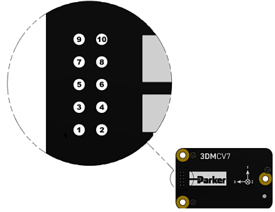
The 3DM-CV7 has the same footprint and nearly the same pinout as the 3DM-CV5 and in most cases it allows more flexibility. However, to support the 3DM-CV7's added functionality, a few changes were made to the physical/electrical interface. The changes are listed below and the impacted pins are highlighted in the accompanying table.
1. The 3DM-CV5's DISABLE pin has been replaced by a fourth GPIO pin (GPIO4). This means that, unlike the 3DM-CV5, the 3DM-CV7 can no longer be disabled through hardware.
2. A PPS can now be input/output through all GPIO pins on the 3DM-CV7.
|
|
||||||||||||||||||||||||||||||||||||||||||||||||||||||||||||||||||||||||
Sensor to Vehicle Frame Transformation
The 3DM-CV7 provides a feature for enabling
Aiding Measurements
The 3DM-CV7 shares many of the same aiding measurement configurations as the 3DM-CV5 but there are some changes:
1. Heading Update Control (0x0D, 0x18) on the 3DM-CV5 is replaced with Aiding Measurement Control (0x0D,0x50) on the 3DM-CV7.
2. The Magnetic Field Magnitude Source (0x0D, 0x4D) command on the 3DM-CV5 has been replaced by the Magnetic Field Declination Source (0x0D,0x43) command on the 3DM-CV7.
3. The World Magnetic Model has been removed on the 3DM-CV7 leaving options of NONE and MANUAL for the command.
Filter Status
The 3DM-CV7 uses the same Status (0x82,0x10) data channel as the 3DM-CV5 to monitor the status of the Estimation Filter, but many of the bit definitions have changed. The new bit definitions expose more information about the current state of the Estimation Filter and the Aiding Measurements. Here are the changes:
1. The Dynamics mode has been removed for the 3DM-CV7 and will always report 1.
2. The filter status flags have been redefined. The changes are highlighted below:
| 3DM-CV5 Bit # | 3DM-CV5 Status Flag | 3DM-CV7 Bit # | 3DM-CV7 Status Flag |
|---|---|---|---|
| Filter State: 0-3 | Possible Filter States: (Startup; Initialization; Running, Solution Valid; Running, Solution Error) | 0-1 | Filter condition (Stable/Converging/Unstable) |
| 5 | Attitude covariance high warning | 2 | Roll/Pitch Warning |
| 5 | Attitude | 3 | Heading Warning |
| 3 | Position covariance high warning | 4 | Position Warning (not used) |
| 4 | Velocity covariance high warning | 5 | Velocity Warning (not used) |
| 8 - 12 | Gyro bias, Accel bias, Gyro scale factor estimate, Accel scale factor estimate high warning | 6 | IMU Bias Warning |
| N/A | N/A | 7 | GNSS Clock Warning (not used) |
| 15 | Antenna offset correction estimate high warning | 8 | Antenna Lever Arm Warning (not used) |
| N/A | N/A | 9 | Mounting Transform Warning |
| N/A | N/A | 10 | Time Sync Warning |
| N/A | N/A | 12-15 | Solution Error |