Vehicle Reference Point Offset
The 3DM-GQ7 can be configured to output the filter's estimated position and velocity in reference to a point on the vehicle. This is called the reference point lever arm and can be configured using the following command: Reference point lever arm (0x0D,0x56) .
How to Measure the Reference Point Offsets
The vehicle's reference point offsets must be measured from the SENSOR ORIGIN of the 3DM-GQ7 to the vehicle reference point. This is done with respect to the Vehicle Frame. For best performance, measure the offsets as accurately as possible.
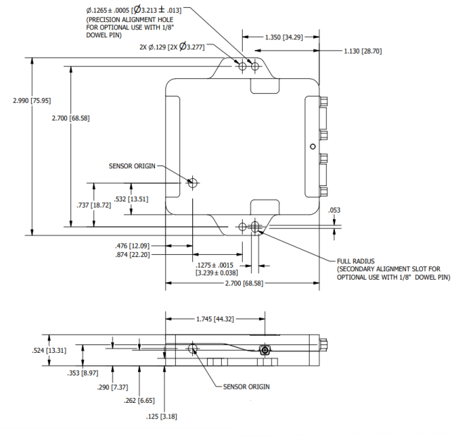
The 3DM-GQ7's sensor origin is shown in the diagram below.
GQ7 Mechanical Drawing: SENSOR ORIGIN
Example: Measuring the Reference Point Offsets in the Vehicle Frame
The following example illustrates how to measure the reference point offsets and enter them in the
Reference point lever arm (0x0D,0x56)
command: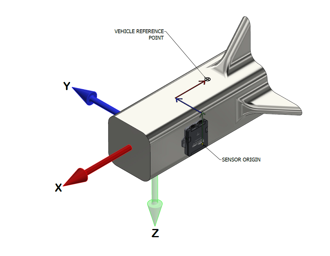
In this example, the green arrow shows the offset along the z-axis of the vehicle frame. It starts at the SENSOR ORIGIN and points in the negative z direction. The blue arrow represents the reference point offset along the y-axis in the vehicle frame. It is in the positive y direction. The red arrow represents the offset along the x-axis of the vehicle frame. It is in the negative x direction.
The table below uses some fictional magnitudes to detail the parameters that would be entered into the Reference point lever arm (0x0D,0x56) command. The signs are correct for the above example.
| Reference point lever arm (0x0D,0x56) Command Parameters | Values | Units |
|---|---|---|
| X offset | -1.32 | meters |
| Y offset | 1.11 | |
| Z offset | -1.64 |